
The demand for high-speed data connection services like 5G develops in tandem with the number of internet users and multimedia apps. To deliver these services, a robust, reliable, and high-performance modem with an efficient structure is necessary. The channel’s inter-symbol interference (ISI) causes severe performance degradation in high-rate transmission. The ISI can be significantly decreased if the receiver has channel equalization. Many equalizers in 5G have been employed to increase the data rate and lower the ISI through channel compensation in the face of inter-symbol interference caused by multipath channels. While linear equalizers, when using the FIR filter structure, have a significant tapped-delay-line (TDL), the nonlinear equalizer class has proven to be quite helpful.
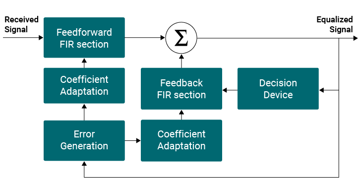
The decision feedback equalizer (DFE), which combines feedforward and feedback equalizers, has a short TDL size and a fast convergence time. Furthermore, in a hostile environment, a decision feedback equalizer can provide optimal steady-state operation. As a result, DFE is increasingly being used in a variety of high-rate data communication applications, including wireless communication, where the QAM modulation format is typically used. The feed-forward and feedback sections of a decision feedback equalizer are connected as follows: decision device, coefficient adaptation block, and error function block. Block Diagram of the Equalizer in 5G IP Core is given below
For cable channels, the Decision Feedback Equalizer supports 64/256-QAM modes. The ISI’s duration is determined by channel parameters and signaling strategy. The FIR filter must cover the ISI time span for a successful equalization operation. Furthermore, the filter length must be selected in order to attain the desired results.
Based on MCNS requirements, the equalization is meant to equalize the multipath channel provided by Stanford Telecom.
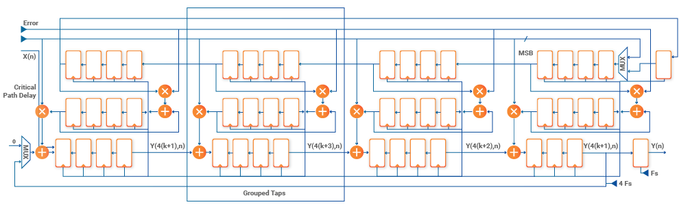
A 16-tap fractionally spaced (T/2) feed-forward equalizer (FFE), a 16-tap feedback equalizer (FBE), and an error monitor make up the equalizer. The 16-taps transposed form adaptive filter, in which both FFE and FBE are implemented, is shown in the diagram below.
Faststream Technologies, on the other hand, shows how to employ Xilinx 7 Series All Programmable FPGAs and SoCs to create high-clock-rate signal processing functionality, which is common in digital radio datapaths.
On a mid-speed grade 7 device, a clock rate of more than 400 MHz can be sustained by using nearly all of the logic slices, more than 90% of the DSP48 slices, and 70% of the block RAMs.
This necessitates the designer to adhere to a set of very basic design guidelines that address both algorithmic and implementation issues. Although nearly all of the slices may be used for pure datapath designs at 400 MHz, only about 75% to 80% of the logic resources (LUTs) are successfully employed, which is mostly due to routing and control set resource limits. A greater LUT usage ratio may be achieved with the next-generation 20 nm UltraScale architecture, which provides dramatically improved capabilities.